Modeling with a Spice Netlist
This tutorial explores the Spice Netlist block in Simba.
This block allows you to include any SPICE netlist, such as:
- a custom netlist you have previously created,
- a Spice model of a powersemiconductor switch, provided by a manufacturer, for example.
Two cases are considered:
For each case, the Simba circuit can be built step by step. I you prefer, the final circuit can be downloaded with the link below:
Download Simba Model of the tutorial
Case #1: Write a Spice netlist from scratch
For this first case, let's consider the circuit below.

It is composed of:
- an AC voltage source of 10 V, 50 Hz,
- a Spice netlist which includes:
- a resistance R_{load} of 1 kΩ,
- a switch controlled by a pulse waveform.
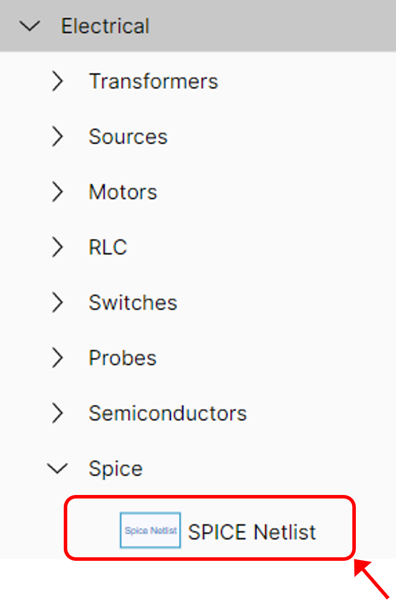
Select Spice Netlist block (#1)
First, select the Spice Netlist block from the library.
Enter Spice Netlist (#1)
Edit the Spice netlist block and enter your spice netlist
info
Lines beginning with '*' are comments
✔ Let's start with the power circuit elements:
- the load resistance of 1 kΩ connected between the nodes vdd and n,
- the voltage-controlled switch connected between the nodes n and the ground.
Spice voltage-controlled switch syntax
S{name} +node -node +control -control model
- +node: positive power node
- -node: negative power node
- +control: positive control node
- -control: negative control node
- model: model
This leads to the following lines:
✔ Let's now define the control signal that drives the controlled switch.
This control is defined with a PULSE signal.
Spice PULSE waveform syntax
Vxxx +node -node PULSE(Vinitial Vfinal Td Trise Tfall Ton Tperiod)
- Vinitial: low level voltage
- Vfinal: high level voltage
- Td: initial delay time
- Trise: rise time
- Tfall: fall time
- Ton: pulse width
- Tperiod: period of wave
which leads to:
✔ Let's now define the switch model with:
- a on-state resistance of 0.5 Ω,
- a off-state resistance of 1 MΩ,
- a switch voltage threshold of 0.5 V,
- and no hysteresis voltage.
Info
SPICE keywords used to define transient or AC analysis settings are ignored. Only the solver settings defined in SIMBA are taken into account.
It is possible to define the parameters of a transient analysis.
✔ Finally, let's define the variables to be saved:
- the control voltage,
- the switch voltage,
- and the switch current.
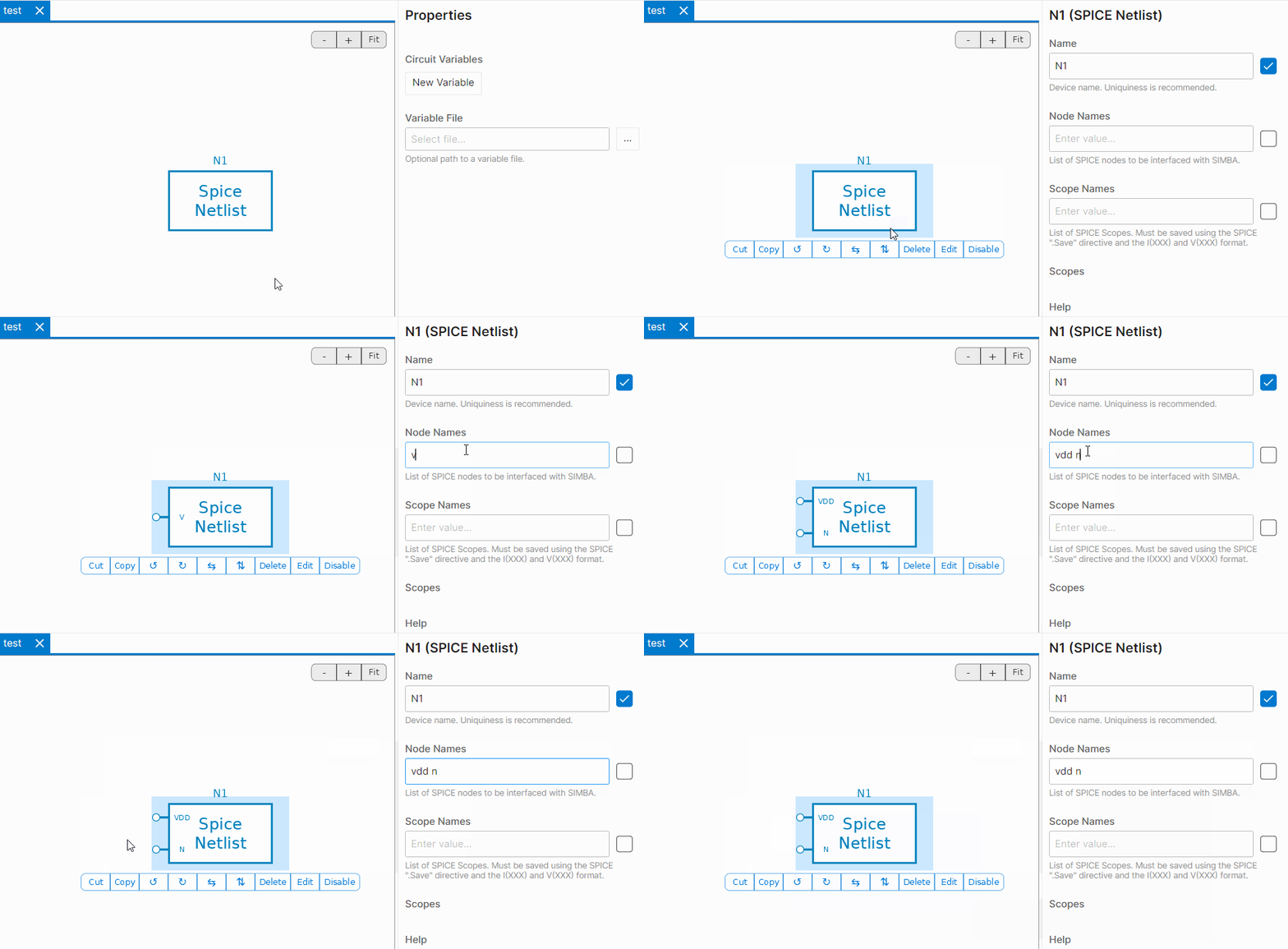
Define nodes (#1)
Define the nodes and the scopes of the Spice Netlist block. These nodes will be connected to the other elements of the Simba circuit.
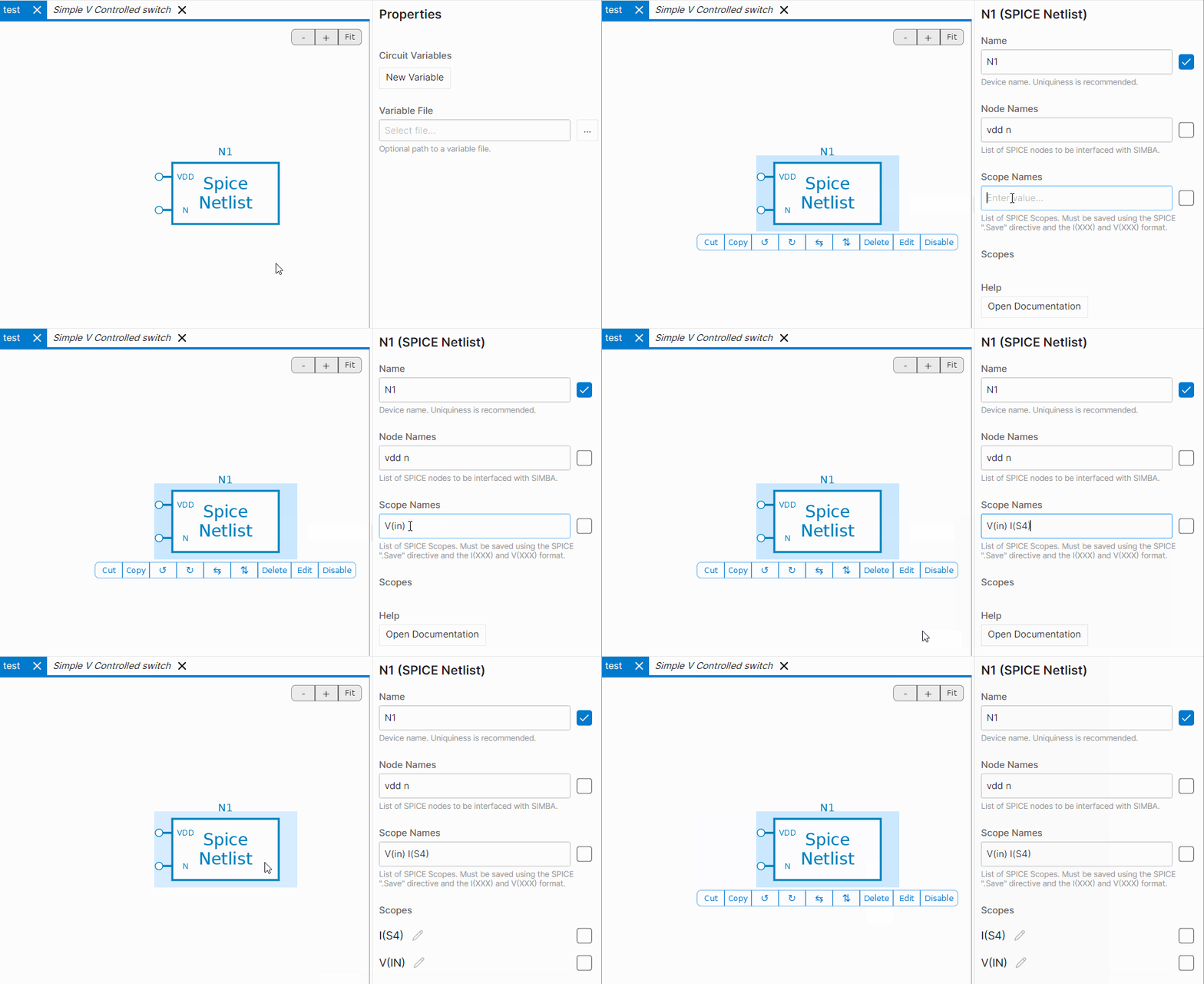
It is also possible to define a list of scope names corresponding to the variables defined in the Spice netlist with the .save directive.
Build Simba circuit (#1)
Let's complete the circuit with a 10 V, 50 Hz AC voltage source and a voltage meter to measure the switch voltage, as shown below:

Simulate & Results (#1)
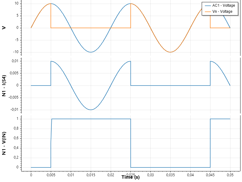
Once the simulation has been run, the following scopes are available, including the scopes defined in the Spice Netlist block, named N1 here.

The different scopes can be plotted has shown below:
- the AC voltage and the switch voltage in a first graph,
- the switch current in a second graph,
- the switch control voltage (V_{in}) in third graph.
Case #2: Get a Spice netlist from a manufacturer and use .subckt directive
For this second case, let's consider the Spice model of a 1200 V SiC mosfet which has been downloaded on Infineon website.
Select Spice Netlist block (#2)
As illustrated in first step of case #1, select the Spice Netlist block from the library.
Enter Spice Netlist (#2)
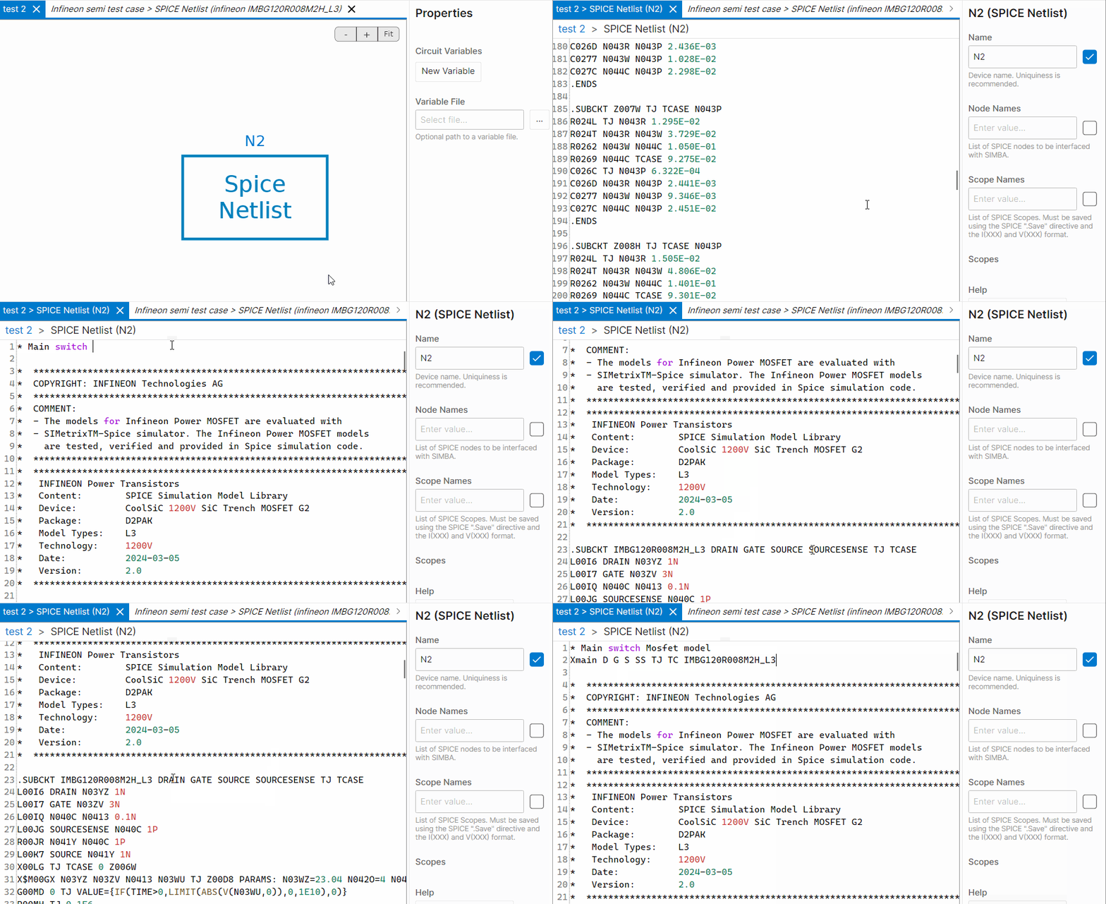
Edit the Spice netlist block and paste the spice netlist from the infineon model. Here, the Spice mosfet model from infineon has been defined as a subcircuit using the .subckt directive.
To use a subcircuit, the subcircuit name which will be used and its nodes must be defined with the command Xmain:
where N1, N2, ...N4 are the nodes of the subcircuit and subcircuitname the name of the subcircuit.
Let's see the example with the Infineon's netlist:
Define nodes (#2)
Define the nodes of the Spice netlist block which will be connected to the other elements of the Simba circuit.
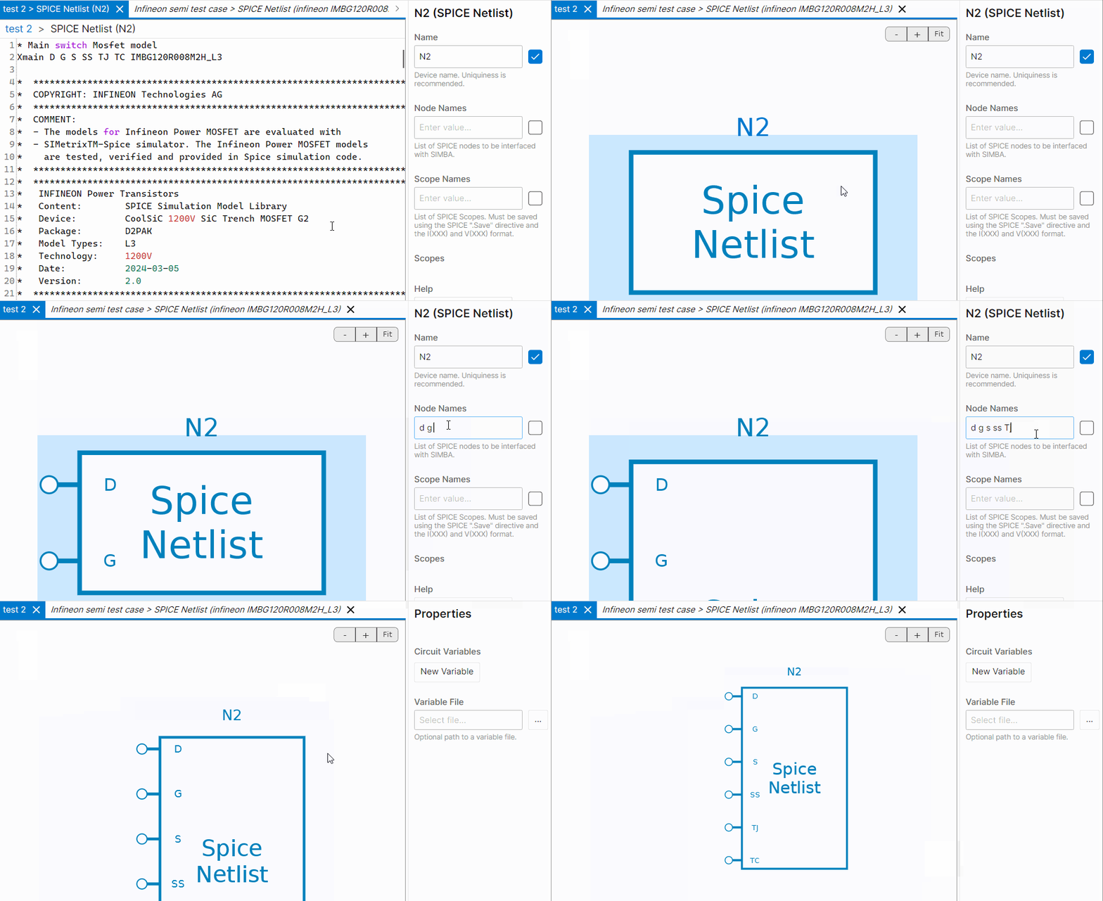
No scopes are defined in this case.
Build the Simba circuit (#2)
Let's complete the circuit with:
- a 600 V DC voltage source,
- a series resistance of 1Ω,
- a temperature source of 89°C modelled by voltage source connected to the junction temperature pin,
- and a gate driver composed of a 15 V 1 kHz AC voltage source.

Simulate & Results (#2)
Define solver settings (here, a minimum time of 1 µs and an end-time of 50 ms have been chosen), run the simulation and plot results as shown below:
- the V_{GS} voltage in a first graph,
- the current i_{DS} through the mosfet (which has been observed through the resistance R_1)

This concludes this tutorial on the Spice netlist block.